tb6612 Motor Control dual-h-bridge
Links and useful resources
Lesson-specific resource links
Concept summary and connections
- Dual H-bridge circuit review
- PWM details review
- Soldering the headers and trying the boards
Board Overview
Let's discuss the pinout for the TB6612FNG breakout. We basically have three types of pins: power, input, and output, and they are all labeled on the back of the board.
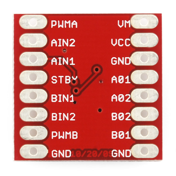
Our boards have the pins laid out differently, but they are all the same otherwise
Each pin and its function is covered in the table below.
| Pin Label | Function | Power/Input/Output | Notes |
| VM | Motor Voltage | Power | This is where you provide power for the motors (2.2V to 13.5V) |
| VCC | Logic Voltage | Power | This is the voltage to power the chip and talk to the microcontroller (2.7V to 5.5V) |
| GND | Ground | Power | Common Ground for both motor voltage and logic voltage (all GND pins are connected) |
| STBY | Standby | Input | Allows the H-bridges to work when high (has a pulldown resistor so it must actively pulled high) |
| AIN1/BIN1 | Input 1 for channels A/B | Input | One of the two inputs that determines the direction. |
| AIN2/BIN2 | Input 2 for channels A/B | Input | One of the two inputs that determines the direction. |
| PWMA/PWMB | PWM input for channels A/B | Input | PWM input that controls the speed |
| A01/B01 | Output 1 for channels A/B | Output | One of the two outputs to connect the motor |
| A02/B02 | Output 2 for channels A/B | Output | One of the two outputs to connect the motor |
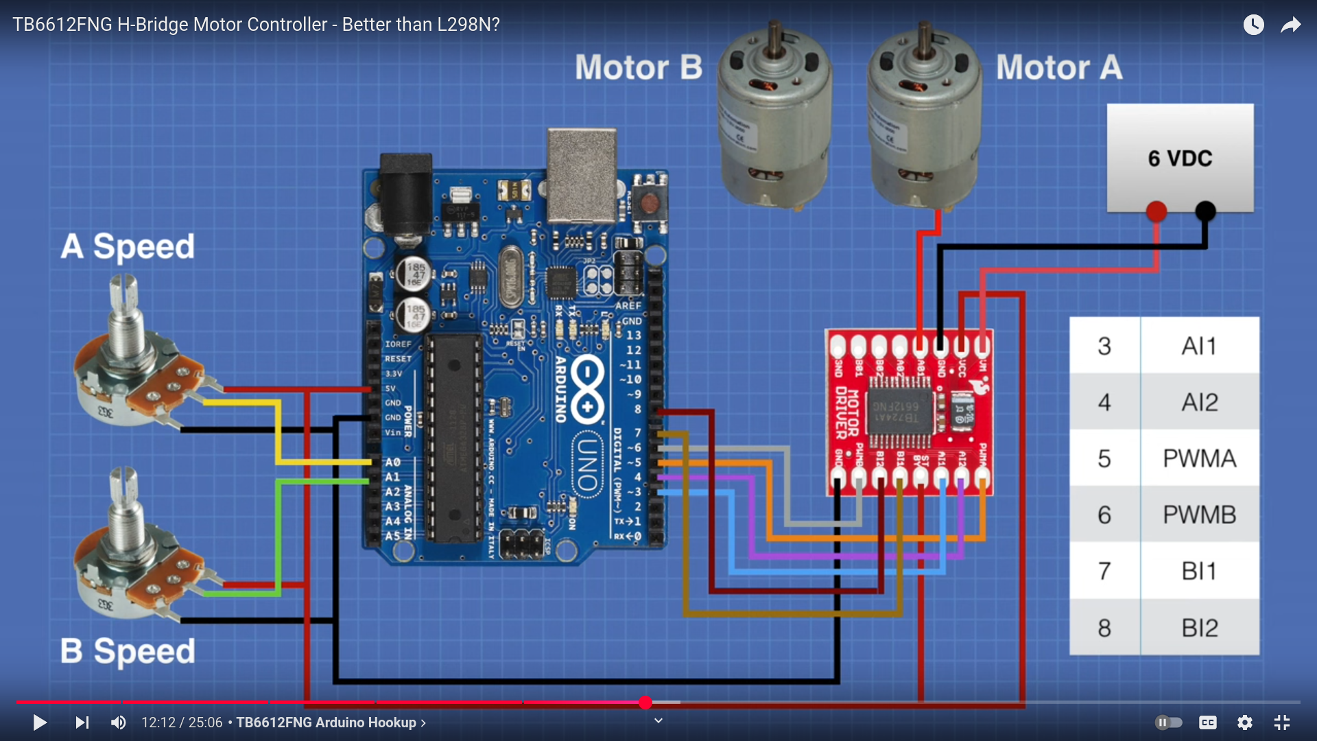
Now, for a quick overview of how to control each of the channels. If you are using an Arduino, don't worry about this too much as the library takes care of all of this for you. If you are using a different control platform, pay attention. When the outputs are set to High/Low your motor will run. When they are set to Low/High the motor will run in the opposite direction. In both cases, the speed is controlled by the PWM input.
| In1 | In2 | PWM | Out1 | Out2 | Mode |
| H | H | H/L | L | L | Short brake |
| L | H | H | L | H | CCW |
| L | H | L | L | L | Short brake |
| H | L | H | H | L | CW |
| H | L | L | L | L | Short brake |
| L | L | H | OFF | OFF | Stop |
Don't forget STBY must be high for the motors to drive.
Hardware Setup
For this demo, we'll use a small chassis with the included motors and wheels as well as an Arduino Pro Mini.
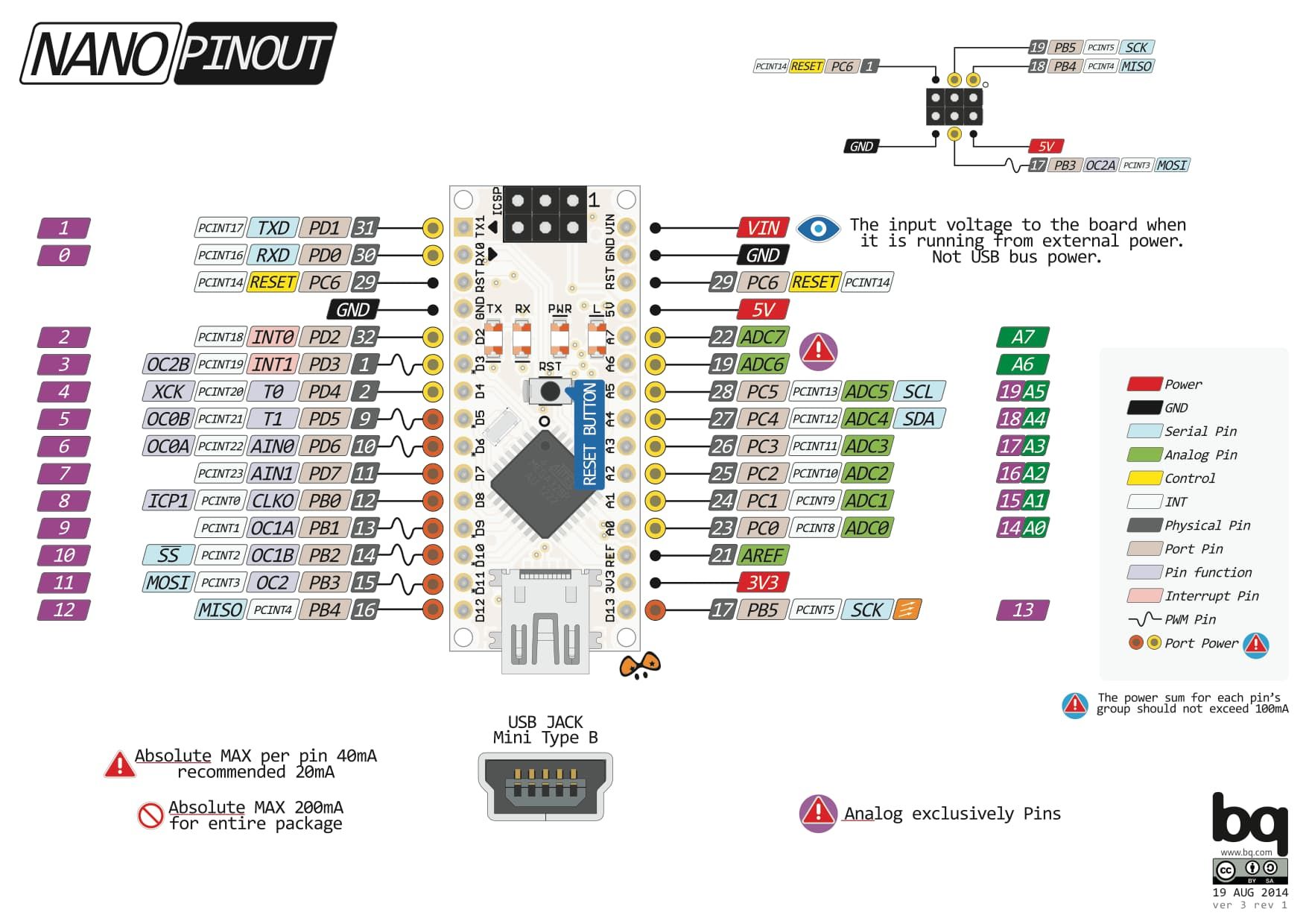
Our power supply for this is the LiFePo4 battery pack, which outputs either 4.5v at the center tap, or 9v with the full tap. We'll use 9v for everything here (the VCC pin should be coming from the arduino, not directly from the battery). Connect the grounds all together. The arduino nano can do PWM on pins 1, 9, 10, 13, 14, and 15, so pick two of those for your PWM outputs.
Put the arduino and the TB6612 across the ditch on your breadboard and wire everything up, then program the arduino to spin the motors!