Building a Photo Gate for Physics
Lesson Plan: photo-gate-design
A photogate is a device that uses a beam of light to record a precise measurement of when an object passes through the gate. We're going to need these for our physics labs soon, so we need to build a few of them.
Photogate Requirements
- Must detect and report the time when an object passes through the gate
- Must allow an object of up to 7" long, 2 3/4" wide, and 5" tall to pass through unobstructed
- Must detect an object as small as a 1/2" diameter steel marble
- Must be able to connect at least four gates to a single Arduino.
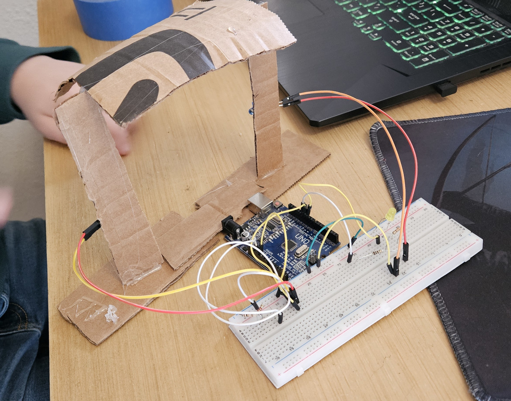
gr7's prototype mockup gate test protocol
- Compile code for arduino
- Make sure there are three remaining Digital I/O pins available after fully connecting the gate. (req. d)
- Measure the height of the sensor. If it is more than 1/2" above the bottom of the track, the test fails. (req c, partial)
- Slide a 7" by 2 3/4" by 5" object through the gate, along the 7" axis of the object. The object must not touch the gate at any point. (req b)
- Pass an object through gate and look at the terminal for time result. It must report a time. (req. a)
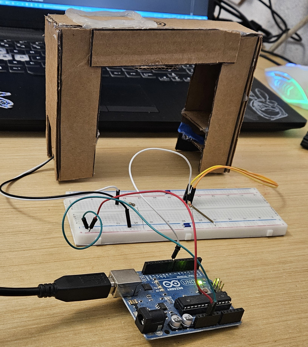
gr10's prototype mockup gate test protocol
- Open and compile code. Verify that it compiles correctly.
- Disconnect 5V pin on arduino, then connect to computer and upload the code.
- Enable serial monitor
- Pass a 7" by 2 3/4" by 5" object through the gate, along the 7" axis of the object. Verify that a time is reported on the terminal. (req. a,b)
- Pass a 1/2" steel marble through the gate. Verify that a time is reported on the terminal. (req a, c)
Design process
Problems to solve:
-
Connecting multiple gates to the same arduno
- Power the LEDs separately with a high-current supply to avoid overloading the Arduino
- Will require one Digital I/O pin per gate to read the signal from the phototransistor
- Will need a power transistor and limiting resistor for each LED and have them wired in parallel to keep brightness even.
- Optionally, could use a second pin to control the LEDs on each gate independently. This doubles the pin count, but there are plenty to use.
-
Adjusting sensitivity/calibrating the output
- We have a fixed voltage divider at the moment. It could be replaced with a 10k potentiometer and 5-10k fixed resistor in series to allow for some sensitivity adjustment. So far it hasn't been necessary.
-
Mechanical design to hold the sensor and LED, as well as the mounting hardware and wires.
- Design should have an easy way to adjust the width and height of the gate structure - make these directly editable dimensions