Differential-steering robot chassis
We are building a pair of line-following robots starting from scratch. The goal will be to have a bot that can detect a one-inch black line on a white background, and drive in a way so that it follows the line around a complex path through the workshop.
- The bot's wheels will be driven by continuous-rotation servos
- The line sensor is an IR obstacle detector board (or multiple)
- The chassis will be 3d-printed based on your own design
Resources
Designs
gr7's design
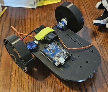
- Large wheels
- Flat, open platform
- Dual-lug mount for servo attachment
- Movable mounting plates for IR sensors to allow vertical adjustment
Issues so far
- Lug on left wheel broke when bot fell off table
- Caster wheel rotation is limited by protruding screw shafts, need to reverse the screws
- Size of bot may make accurate maneuver difficult, because the IR sensors are a long distance from the pivot point.
gr10's design
- Large wheels
- Box-like enclosure
- Through-hole mount for servos
- Slotted attachment for IR sensors to allow vertical adjustment
Issues so far
- Redesign required on wheel attachment due to impossibility of assembly initially (no way to reach the screws)
- Through-hole mounts for servos are difficult to 3D print due to large bridging requirements over top of hole, had to make big adjustment to account for that
- Several problems due to poor bed adhesion on the printer, cause isn't certain but flipping PEI plate has resolved it for now.
- We seem to have a problem with either the quality of the fitech fs90r continuous rotation servos
- They are not still at any value near 90
- Their rotation is inconsistent
- According to the docs, they should have no motion if the pulse width is 1.5 ms, so maybe we should try servo.writeMicroseconds(1500), and use our map function to manually map the -1...1 interval of speed into the 1000 ... 2000 range of microsecond timings.
- I am wondering if continuously writing the value with the servo is causing it to reset its internal timing and messing up the pulse interval and width
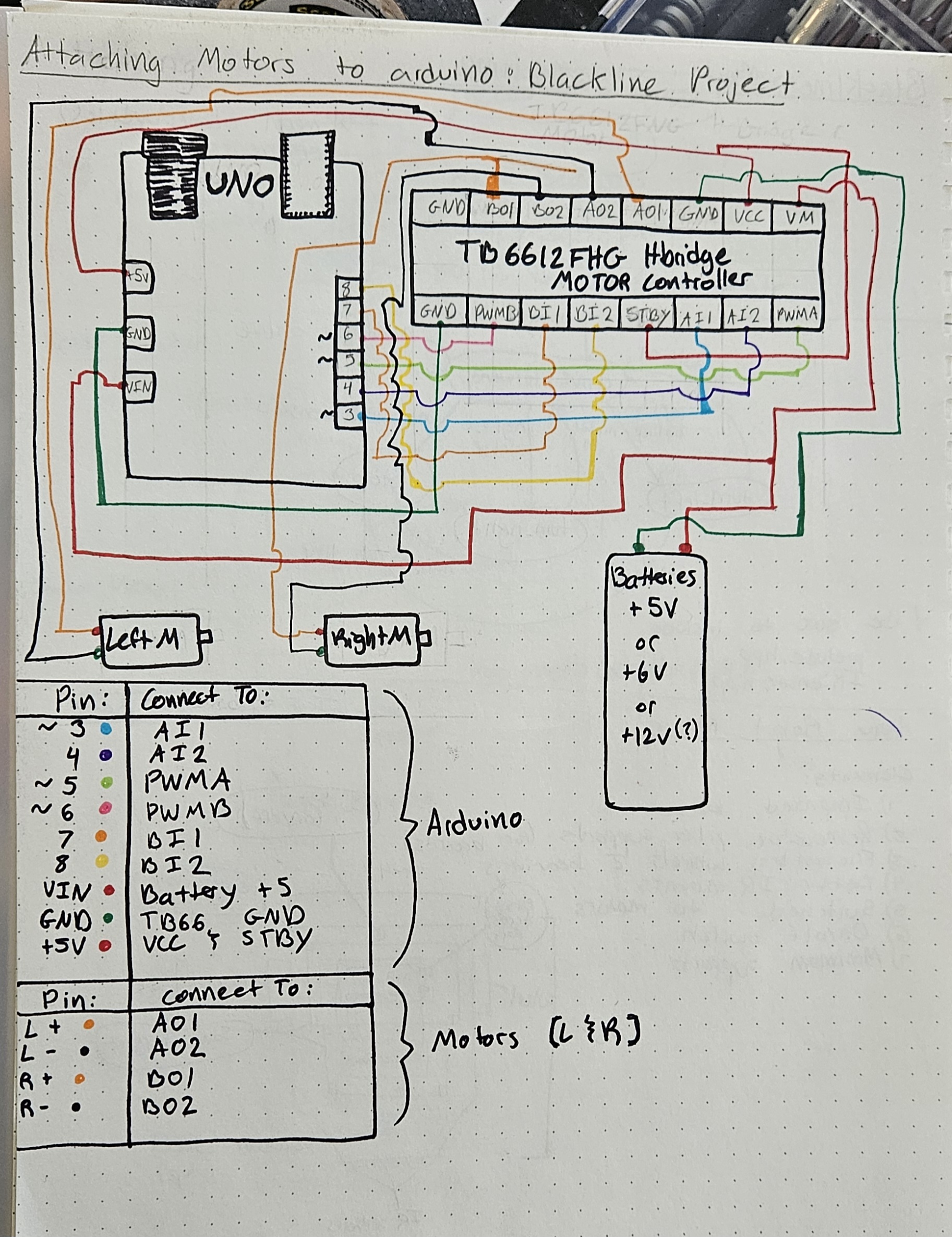
- Resolution: The servos themselves are the problem. They just don't work well, because they're cheap. We switched to plain DC motors with PWM control and all is well.
- We have learned that using pin 13 as the input from the IR sensor is not a good idea.
- The IR sensor seems to put out an analog voltage rather than a digital signal as we expected
- Pin 13 has a resistor and LED attached to it on the board, so it has some voltage drop built in
- When we're working with signals close to the threshold anyway, it's too hard to tune the IR sensor board with that extra LED load applied.
Next steps
- 2025-02-04 Assemble bots, wire and connect battery, and test the drive method.
- Add methods for turning
-
- Add method for steering to follow line
- [ ]